Solder Paste Measurement: A Yield Improvement Strategy
![]()

Start a Yield Improvement Strategy at the Beginning of the Line
Studies show that the average first pass yield is 80% for electronics manufacturers using SMT. A “battle-scarred” process engineer once said that even before a solder joint reaches the reflow oven, it has already been formed. So look at areas for improvement earlier in the production line. Most experts agree that controlling solder paste printing is a key to high yield production. Some even say that as much as 50% of all soldering defects can be traced back to the deposition (printing) process. That’s not surprising, since its been reported that there are approximately 40 variables in the solder paste printing process. Controlling such a volatile process requires identifying characteristics that will predict process performance and finding a suitable tool to measure those characteristics.
Why Measure Solder Paste?
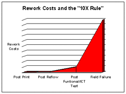
Consider the cost of rework at each stage of assembly. Washing and reprocessing a poorly printed board will take much less time and resources than repairing solder defects on a fully populated, reflowed board. A quick rule of thumb for estimating rework costs is the “10X Rule”. Simply, it states that rework costs at each stage of the assembly process will be 10 times greater than at the previous stage. For example, if a print failure costs only $.50 to correct, leaving it to be fixed after reflow will cost $5.00. That same failure left unchecked until after ICT/functional test (when the PCB is fully populated or mounted in an assembly) will cost $50.00 to fix. And if a poorly printed (and reflowed) solder joint fails in the field, the costs associated with resolving the problem and soothing the customer could run $500.00, or more. It’s easy to see how the savings attributed to finding defects as early as possible in the process (i.e. at the printing stage) can easily justify the costs associated with obtaining solder paste measurement equipment and implementing a paste inspection strategy.

Choosing the Equipment and Inspection Procedure for Your Company
Solder paste inspection can be as uncomplicated as having an operator monitor the printed boards as they exit the printer. You could install a ring light magnifier or a non-graduated microscope to help the operator distinguish the tiny features of PCB designs incorporating very fine pitch and µBGA. The good news is that this method requires only minimal training and capital purchases. The bad news is that the subjective nature of purely visual inspection means you can’t expect a high degree of repeatability from operator to operator. In addition, visual inspection does not produce any quantifiable, measurable data, meaning that if your operator quits or moves to another work area, you lose the recipe to a controlled printing process.
Optical or laser-based instrumentation can, on the other hand, produce measurable and reproducible information on the dimensional characteristics of solder paste deposits, such as height and volume. Here, you have several options from which to choose, from simple off-line manual, laser-based or structured light-based systems to fully-automated, in-line machines installed between the stencil printer and mounting machine. In addition, some printer manufacturers offer in-printer inspection capability as an option. It’s frankly a matter of the performance you require versus the cost you can justify.
Developing a Plan to Implement Inspection…Address these Questions:
- What is my current “first – pass” yield? The term “first-pass” indicates that no rework or touch-up has been performed on the boards before the yield is calculated.
- What would you like the first-pass yield to be? Of course, in an ideal world, one would like 100% yield. It’s really a question of economics, because the closer your goal is to that magical mark, costs to obtain it grow exponentially. Your price (what you sell the end product for) is usually is a sum of the cost of materials, equipment and labor plus profit. But in the real world, most manufacturers make anticipated yield part of the price equation. One industry consultant quotes a study that revealed a correlation between several manufacturers’ average first-pass yields and profitability. If your current first-pass yield is lower than your original projections, a yield improvement strategy including paste inspection will help you to meet your target margins. If your process meets your initial yield and margin estimates, any improvement in yield will fall to the bottom line as an improvement in profits.
- What percentage of your soldering defects are printing defects? Shorts and opens are obvious, but don’t forget that since the tackiness of solder paste enables it to act as a glue to hold components in place prior to reflow, a percentage of missing or mis-oriented components are caused by insufficient paste.
- What are the costs associated with soldering defects? Here, you may want to consider more than just labor, equipment and materials, but also the affect rework and scrap has on the whole company, not just the manufacturing department. What’s the financial impact of rework and scrap on your quality or ISO procedures, your procurement process, deliveries and shipments, sales and customer support?
- What can you afford to spend on inspection? Instrumentation is priced from around $10K for simple off-line manually operated systems used by line operators to fully automatic, in-line machines priced from $100K-$300K requiring engineering talent to manage.
- What kind of ROI (Return on Investment) does your company look for? A solder paste inspection machine is like any other piece of equipment you purchase for production. It’s an investment. Calculate how much your company spends on soldering defects within a reasonable time frame. Most companies expect payback within a year. Weigh a year’s worth of soldering defects against the cost of purchasing and operating paste inspection equipment. Admittedly, solder paste inspection won’t help you to solve all your soldering problems, but consider how much you could afford if a large percentage of your rework and scrap disappeared.
The Impacts of Solder Paste Measurement on Your Production Process
The success if instituting any new procedure and equipment into a manufacturing process can be difficult to obtain, especially if they’re complicated or subjective. As mentioned earlier, paste inspection systems fall into two categories, off-line manual and in-line automatic. The success of either type will rely on the skill and training of your production staff.
Manual off-line systems, while inexpensive and easy to learn, calculate characteristics like paste height and width only after the operator moves on-screen cross hairs or cursors into position over a magnified video image of the paste sample. This means the operator must guess where to place the cross hairs. Depending on the amount of training done to correlate operator eyes to what they see on the system screen, measurement repeatability is usually fair to poor.
The in-line automatic systems use imaging technology similar to the off-line instruments, but they also incorporate machine vision and robotics to take the operator out of the inspection and handling loop. These expert systems are powerful and repeatable, but also complex. Typically, an engineer must be assigned to program the equipment and interpret the data it provides. This can be an additional expense to an already lofty investment.
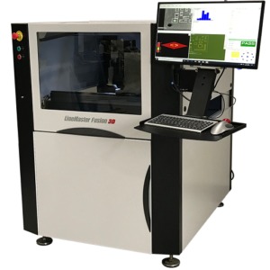
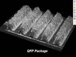
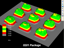
Understanding that the issues with existing instrumentation listed above has kept a number of companies from developing a solder paste inspection strategy, ASC International recently introduced two affordable bench-top 3D measurement systems that automatically measure critical paste characteristics such as volume and height and are easy to learn and use. Operators can be trained on either of these systems within a matter of minutes and the automatic measurement capability removes the guesswork associated with manual, off-line systems. In addition, one of these systems is capable of displaying a color 3D map of the measured paste, providing operators charged with setting up and operating the solder paste printer with a qualifiable, as well as a quantifiable, look at the performance of the process.
The First Steps to Yield Improvement
The first step is to identify the variables in paste printing that have the greatest impact on first-pass yield and determine the targets and acceptable ranges particular to your products and processes. As mentioned earlier, most experts agree solder paste height and volume are the most critical characteristics. If you are unsure of the appropriate specifications, start with targets based on the stencil thickness (for height) and stencil thickness times the aperture size (for volume). Set reasonable upper and lower control limits (+ 25% and -25 % of the targets, for example). Next, check the printer set-up by printing and measuring a test print on a flat sample surface. A piece of white poster board will work. Take sample measurements at critical locations (the corners of fine pitch sites, BGA and µBGA sites, etc.) in addition to gathering readings at the corners and the middle of the complete print area, checking for parallelism. Once you are confident in the printer set-up, perform a pilot run. Record measurements on every PCB in the pilot lot. If a print failure is found (i.e. exceeding your selected control limits) wash the sample, adjust the printer and reprint. Process the boards through reflow.

After reflow, inspect and calculate the yield. Adjust your process limits based on the defect analysis. For example, if post reflow inspection identifies shorts, lower the upper control limit. If opens are found, consider increasing your targets. Don’t be surprised if the targets based on the stencil design need to be revised. There may be several reasons for this, including PCB design, the thickness of solder mask, tin/lead plating on pads, reference surface used to calculate height, and board warp. Remember, repeatability is the key to consistent results. Following this simple procedure to tune the process will put you on the right track to yield improvement.
Improved Quality = Improved Profitability
Until recently, inspection equipment and procedures took a back seat to more production- oriented machines and processes. Manufacturers are now beginning to realize high yields not only reflect quality, they also translate to higher profits. When considering where to begin a yield improvement strategy, bear in mind that it is easy to find testimonials describing how controlling the printing process has provided the greatest returns.


For more information, contact ASC:
ASC International
830 Tower Drive
Medina, MN 55340 USA
Tel: 763-479-6210
Email: info@ascinternational.com